
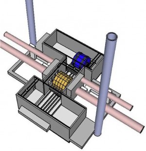
Layout of the ILC detector cavern for the American region. The detectors push and pull into the common interaction region on platforms. The parking areas need to offer sufficient space to open and service the detectors. (Source: T. Lackowski)
If you are planning to build a home for your family, there is an important ingredient that you will need: translucent paper. Sooner or later in the planning stage, you will have the first blueprints from your architect, and if you are lucky, they already represent to a large fraction what you imagined your new home would be. But then you start to have a closer look and you start to optimise. What would happen if this wall would be shifted somewhat? Or will your new cupboard really fit into that niche? Then the translucent paper comes into play. You put it over the original drawings and you copy them. On the copies you do all the changes that you think are needed. In addition you would probably cut out forms out of an additional sheet of paper that represent scaled versions of your furniture and you test how you would arrange that in the new rooms. OK, you might have noticed that I used to do these things the old-fashioned way. Nowadays I am sure there is an app that would help you with this process.
But in the end, it is an optimisation process that you need to do. You have to check your requirements and you have to take the hard boundary conditions into account: maybe geological reasons forbid you to build a house with a cellar. Or maybe official regulations tell you what shape the roof of your new house has to have. And in the end comes the decisive boundary: your budget. In addition, it is a collaborative process – at least in most cases. Surely your family has a word to say in the creation of the new home.
Designing an experimental environment for the ILC detectors is in certain points rather similar. The underground and surface buildings at the interaction point need to be optimised to accommodate the detectors so that they can be assembled, operated, and maintained with highest efficiency. The requirement for efficiency is probably one of the biggest differences between the design of an underground experimental hall and a family home. Building the ILC binds so many resources that we cannot afford to waste money, time or integrated luminosity.
The underground experimental halls are in the focus of the collaborative efforts between both ILC detector concepts, SiD and ILD, the Machine-Detector Interface Common Task Group, the Beam Delivery System Group and the Conventional Facilities Group. These halls are the most complex underground buildings in the ILC and therefore need to be scrutinised for efficiency. The design of the experimental hall shown in the Reference Design Report was simplified and not optimised to the operation of the two detectors in the push-pull system. The basic functional requirements of the interaction region had been agreed upon in 2009, but only the following R&D studies on all relevant issues of the push-pull system, the evolving detector design and the better understanding of the requirements triggered an optimisation process that has been discussed at many real and virtual meetings. A major milestone was the agreement in early 2011 that for the push-pull system the detectors should be placed on big concrete movable platforms. Experience from existing high-energy physics experiments, for example DESY’s HERA detectors, and detectors at SLAC, KEK and of course CERN’s LHC, was very helpful. Joint CLIC-ILC studies on geological issues and on a detailed design for the platform based push-pull system have been exploited.
The design of the underground hall for the non-mountain sites of the ILC, such as the American or the European sites, is now rather advanced. A common layout of the cavern has been agreed upon and should be part of the ILC baseline in the Technical Design Report (see figure above). This design relies on the fact that the detectors would be mainly assembled in surface buildings, similar to what was done for CMS at the LHC. The big pre-assembled detector parts would then be lowered through a big vertical shaft into the experimental cavern (see photo below).
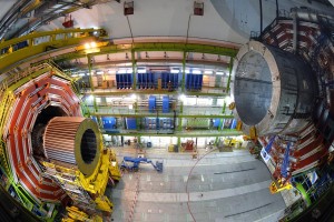
Lowering of the CMS parts into the experimental cavern. The ILC detectors are of similar size. Image: CERN
The focus of the work is now on the specifications of the mountain sites for the ILC that are under study in Japan. These sites would not allow for vertical access via shafts, but the experimental hall would be reached by horizontal access tunnels of about 1 kilometre in length. A modified detector assembly scheme needs to be followed under these conditions as the transport capacity in the access tunnel limits the mass and size of the parts. In consequence, enough underground space needs to be provided to allow for the assembly of the detectors out of these smaller parts.
It is clear that this kind of design work cannot be done with translucent paper anymore. The bases of these evaluations are the 3-D CAD models of the detectors and the underground halls that are organised in the ILC engineering document management system. But the basic principles are the same: how does the equipment fit into the available space and how do we keep the requirements while optimising the system to high efficiency? The upcoming KILC12 workshop will be an important step on the way to find the final underground hall design for the TDR.

I have few questions:
Q1: I cannot see ‘pac-man’ interface in the 3D-CAD picture (I can see no room for it). Was it discontinued? How about sites in Japan?
Q2: Are there large vertical access shafts above both parking halls (for American or European sites)?
Horiuchi-san,
Here’s the response from Karsten Büsser:
Q1: We need the pacman radiation shielding – or something equivalent, in any case, also in Japan. The hall model in the figure does indeed include the space for the pacmen shields. Their parking positions are the niches left and right from the place where the tunnel enters the hall. The shieldings themselves are not shown.
Q2: The design for the non-mountain site halls (Europe and America) currently foresees five vertical access shafts. One big access shaft (18-metre diameter) directly over the interaction point will be used for the assembly of the detectors. Two smaller ones (8-9 metres) are in the parking halls (one in each) and will be used for maintenance purposes and for service lines. And then there are two additional small shafts for elevators and safety egress.