The design of the International Linear Collider has recently changed from featuring two tunnels to just one. This means many aspects of the tunnel design have to be re-thought – including the distribution of the radiofrequency power, the acceleration technology of choice for the ILC’s superconducting cavities. In addition to the klystron cluster scheme, the power-delivery system for radiofrequency cavities introduced in last week’s ILC NewsLine, an alternative scheme is being developed at KEK, Japan.
Since 70 percent of Japan is mountainous, naturally the candidate sites are considered to be in a mountainous area. It would not be practicable to have large buildings on the surface. Also, the shaft pipes in the klystron cluster scheme, which will feed power underground, are planned to have a fixed length. This wouldn’t fit into a mountainous area either, where sloped tunnels with different lengths instead of vertical shafts to reach underground will be needed.
“So we proposed a very simple solution for the single-tunnel plan, the distributed radiofrequency system (DRFS),” said Shigeki Fukuda, the high-level radiofrequency (HLRF) specialist at KEK.
DRFS is a complete single-tunnel plan and there are no extra HLRF-related facilities on the surface. All the equipment to generate the radiofrequency (RF) power will sit inside the underground tunnel, together with the RF waveguide. In this scheme, many small HLRF units will provide RF power, and each unit will feed two or four superconducting cavities. How many in total? The ILC will have more than 16,000 superconducting cavities, which means that it is necessary to make about 8,000 klystrons and 975 DC power supplies and pulse modulators (including 325 backup units).
The plan is to use three different kinds of cavity units coming from three regions. This feature will make it possible to appropriately operate those cavity units with different characteristics. In the present technology of manufacturing superconducting cavities, their quality varies greatly, and scientists have to accept the field gradient variation of 31.5 megavolts per metre plus or minus 20 percent. DRFS technology will enable engineers to appropriately operate those cavity units with the possibility of adjusting to individual characteristics. “It is also useful for dealing with the deterioration of units after installation,” said Fukuda. “If some cavities quench or couplers fail, others are operated instead of deteriorated units, and the influence of these effects becomes negligible.”

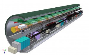
Bird's eye view of DRFS in a single tunnel. Required components except for the infrastructure are all installed in a single tunnel.
The klystron adopted in the DRFS scheme is called the modulated-anode-type klystron. “This type of klystron has superior cost effectiveness, and actually, is adopted in many big facilities such as J-PARC (Japan Proton Accelerator Complex, Tokai, Japan) or the Spallation Neutron Source in the US.”
Since the HLRF system is costly in general, reducing the total numbers of RF units tends to become one of the main topics in the cost-reduction discussions. And naturally, there are concerns that DRFS may be too expensive a choice. “We are trying to develop cheaper manufacturing ways through mass production, and we are confident that it is possible,” says Fukuda. Also, small klystrons have potential applications in many fields if they can be manufactured in reasonable way: for example, they could be an RF source for a medical accelerator, perhaps for use in PET or cancer therapy, or an RF source for handy X-ray inspection. It is also applicable as an RF source for an energy recovery linac or the proposed Project X at Fermilab, US.
There is another concern with DRFS: the faults rates. Since the number of units is large, it might be a good guess that the number of failures will be similar. “In order to keep or even raise availability, we showed that the realistic mean time between klystron failures is long, and it is not a serious problem if there are two maintenance terms a year,” Fukuda believes. The team also plans to have backup units of power supplies and modulators. “We calculated that the probability of having a serious failure, which would cause a stop of operation, will be very small,” said Fukuda.
Important tasks for the team are first to complete the prototype DRFS currently under setup at KEK and then to carry out some further R&D to reduce the cost.
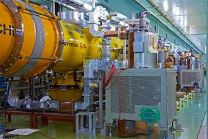
The KEK team introduced the first DRFS system at the S1-Global experiment at KEK. The system comprises two DRFS klystrons connecting with a DC power supply and pulse modulator, the minimum unit of DRFS to demonstrate the feasibility of the DRFS system. This test will be performed over three weeks in February. After that, one DRFS unit will be operated through 2011 for the so-called quantum beam project. Larger-scale tests with the DRFS system consisting of four to five DRFS klystrons with a DC power supply and a modulator are planned at the phase-two plan for KEK’s Superconducting RF Test Facility from 2012 to 2013. “At the same time we continue to have an R&D aiming for more cost reductions,” said Fukuda.


Recent Comments