
Heat waves aren’t always a bad thing. For scientists working on accelerator cavities, they provide a simple way to locate hard-to-see surface defects, which can turn an otherwise superconducting cavity into a dud.
Cornell University’s second-sound detection system homes in on a cavity defect, such as a pit hiding in the cavity wall, by tracking the heat that emanates from it once the cavity reaches a certain accelerating gradient.
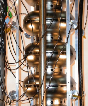
An ILC-type cavity soon to be tested for defects using second-sound detection. The sensors, oscillating super-leak transducers, are the small metal discs connected to cables. Image: Zach Conway.
“It’s turned out to be a very convenient, fast and effective way of isolating the defect location to less than an inch,” said Don Hartill, member of the SRF (superconducting radiofrequency) group at Cornell University. Because it calls for very little equipment, it’s also inexpensive.
In second-sound detection, sensors are positioned outside and around the cavity. The sensors and the cavity, powered by a radiofrequency transmitter, are submerged in a bath of liquid helium.
When the voltage gradient of a defective cavity is cranked up past what the cavity can handle, it quenches – goes from superconducting to normal-conducting – and the cavity suddenly loses its stored energy. At the same time, the cavity’s temperature rises at the defect responsible for the energy loss, so unmasking the pit as ground zero for a heat wave.
Together, the strategically placed sensors act as a kind of positioning system to locate the hot spot that marks the defect’s whereabouts.
“With this system, we can very easily detect where a quench comes from,” said Georg Hoffstaetter, head of Cornell’s SRF group.
Here, heat propagates in unfamiliar ways because of a surprising property of liquid helium whose temperature is lowered below its so-called lambda point, 2.18 kelvin. The heat doesn’t fill up the helium the way heat from a fireplace fills up a room. Rather, it’s a pulse that advances through the helium like a sound wave, slowly making its way towards the sensors at about 20 metres per second.
That pulse is the second sound, and it doesn’t refer to an echo. It’s a mathematical term in the equation that describes heat when liquid helium is cold enough.
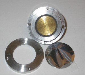
Components of an oscillating super-leak transducer. The plastic film with micrometre-scale holes is shown in the lower right corner. Image: Zach Conway.
Below its lambda point, liquid helium takes on a split personality. Ultra-cold liquid helium has both a normal part and a superfluid part. The superfluid component has zero viscosity and can pass through the tiniest pores without friction. The normal helium component can’t.
When the helium’s temperature changes, so do the relative amounts of the two components, like pans in a beam balance – the overall density of the fluid remains constant.
The sensors that detect second-sound waves, called oscillating super-leak transducers, are capacitors. One capacitor plate is an aluminium-coated plastic film with micrometre-scale holes. The superfluid, able to move freely through the holes, behaves as if the film wasn’t even there.
When the heat pulse arrives at the sensor, the rise in temperature results in a drain of superfluid from the capacitor through the holes. Normal fluid from outside can’t push its way through the holes to compensate. Since ultra-cold helium can’t tolerate an overall density loss, the capacitor volume diminishes to make up for it. The first plate is drawn closer to the second (a solid metal), and – voilà ! – the capacitance goes up and the voltage goes down.
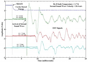
A read-out of the sensor signals. The top curve indicates the onset of the quench, when the cavity’s transmission power goes to zero. The second, third and fourth curves show when the temperature wave, propagating through liquid helium, reaches three different sensors. The precipitous drop in each curve indicates the arrival of the wave for that sensor. Image courtesy of Georg Hoffstaetter.
That’s the signal that temperature wave, which originated at the quench, has arrived.
Researchers measure the time from the sudden powering down of the cavity to the onset of the wave at the transducers, so deducing the distance from each transducer to the culprit area. With multiple transducers, the distances uniquely determine the quench spot.
“It’s as if you make a string as long as the travelling distance, and you check where all the strings from the sensors meet,” said Hoffstaetter. “That’s where the quench happened.”
Right now, Cornell can resolve the quench spot to about two centimetres. Beyond that, a mirror system and a telescope allow researchers to zoom in to a resolution of a few micrometres if necessary.
The idea to use second-sound detection for cavity research originated in an advanced laboratory course taught by Hartill at Cornell’s physics department. Second-sound is in general used to perform tomographic studies with liquid helium.
“A few years ago, it dawned on me that we could actually use it for our ILC test programme,” he said. The Cornell team has been honing the system ever since. They recently increased the number of transducers around the cavity from eight to 16, which means more of them can be positioned in a direct ‘line of sight’ from the quench location.
The Cornell-developed transducers are now being used at laboratories around the world: Argonne National Laboratory, Fermilab and Jefferson Lab in the US, IHEP in China, INFN in Italy and KEK in Japan. DESY in Germany also uses transducers based on Cornell’s design.
There’s a reason for the popularity of second-sound quench detection. The only thing that surprised people about it, said Hartill, was “how easy it was to use.”
Recent Comments