In an opening plenary session at ALCPG11 in Eugene, Oregon, I summarised the history and status of the process towards a new baseline for the design of the ILC. I present only an overview here.
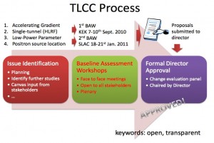
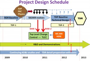
The year-long Top Level Change Control (TLCC) process was completed just in time for the Eugene meeting and is shown in Figure 1, along with where this fits into the present ILC project design schedule (Figure 2).
This new baseline is the starting point for the Technical Design Phase 2 (TDP2), which culminates in the updated Technical Design Report (TDR) by the end of calendar year 2012. This is a major milestone in the ILC/Global Design Effort schedule, though it is expected that technical R&D and systems demonstrations will continue well beyond this date.
There were four major topics or themes in the development of the new baseline: technology choice, simplification of civil design, beam parameters and systems design choices. The common threads were performance and cost containment. These have been extensively studied over the past 15 months, reviewed in baseline assessment workshops and formally approved by a change evaluation panel chaired by the director. Even after all of this work, the new design needs detailing and integration; this work began at the Eugene meeting. Over the next twelve months there will be system-by-system specialised workshops to finalise and document the details of an updated design for the TDR, which will include updated cost estimates.
In the area of technology choices it was agreed that the average accelerating gradient for the installed superconducting cavities would remain at 31.5 megavolts per metre as in the RDR, but also that a range of gradient would be accepted at the level of +/- 20%. This will enable realistic studies of mass production models and costs and the optimisation of the radiofrequency (RF) power systems to efficiently match this spread in gradient in realistic operating scenarios.
For the civil engineering baseline, a single tunnel design has been adopted for the linacs by removing the support equipment tunnel. This change is supported by the development of one or both of the new radiofrequency powering schemes, the distributed RF system and/or the klystron cluster scheme. The linac housings now amount to one-third instead of two-thirds of the underground tunnels and this design approach can be adapted to almost any site.
A major impact on cost containment (equal to five to six percent of the total project cost) has been achieved by adopting a beam parameter set with half the number of bunches in each bunch train. This reduces the beam power and all the costs associated with providing it. It also enables using damping rings for half the circumference, which amounts to 3.2 kilometres in contrast with 6.4 km. The luminosity is recovered to the previous values with stronger focusing in the final focus, which means tighter beam-beam alignment tolerances and therefore some increase in risk. Many systems that are difficult to later upgrade, such as high-power beam dumps, continue to be designed for handling full power, defined as the power at one-teraelectronvolt (TeV) centre-of-mass energy. The damping ring tunnel will be sized to allow the possible future installation of a second positron ring where, with two 3.2-km rings, one can accommodate the original longer bunch train while maintaining the same spacing between bunches. This allows for possible luminosity upgrade paths without major civil construction or a luminosity and energy upgrade to 1 TeV with longer linacs. This continues to be part of the site specifications. An energy upgrade scenario from 0.5 to 1 TeV will be part of the TDP2 studies and the Technical Design Report.
The largest system design changes are associated with the move of the positron source systems from mid-linac (RDR design) to the end of the linac, overlapping and sharing tunnels with part of the beam delivery system. This change reduces the overall tunnel length required and simplifies the design and operation of the linac system itself. However one must still address the problem of maintaining a constant yield of positrons over a large range of final operating energy. With an undulator-based positron source, which would enable the production of polarised positrons, the positron flux is a function of both the intensity and the energy of the electron drive beam. We desire a final positron charge per bunch (that is, the charge per bunch at the interaction point) equal to that of the electron beam. To achieve this, we have adopted a solution for operating centre-of-mass energies less than 250 GeV, which differs from that in the reference design. That is, at the lower energies of less than 150 GeV per beam, we will operate the electron linac and injector systems at ten hertz instead of five, with half of the pulses producing positrons and half going to the interaction region. In this mode of operation the damping rings are required to have twice the damping rate. This is achieved using an increased number of wiggler magnets in the rings and with a commensurate increase in RF power supplied to the beam.
As magnet technology continues to advance, shorter-period, higher-strength undulators may become available and the optimisation of positron production for all energies, from those attained at the Large Electron-Positron Collider (CERN’s former collider) on up to one TeV, may be done more simply by variations in the length and strength of these components.
Regardless, we have a new baseline from which to develop the TDR for an ILC that is ready to attack, over a broad energy range, the new physics that we believe will be uncovered by the LHC by the end of 2012.


Recent Comments